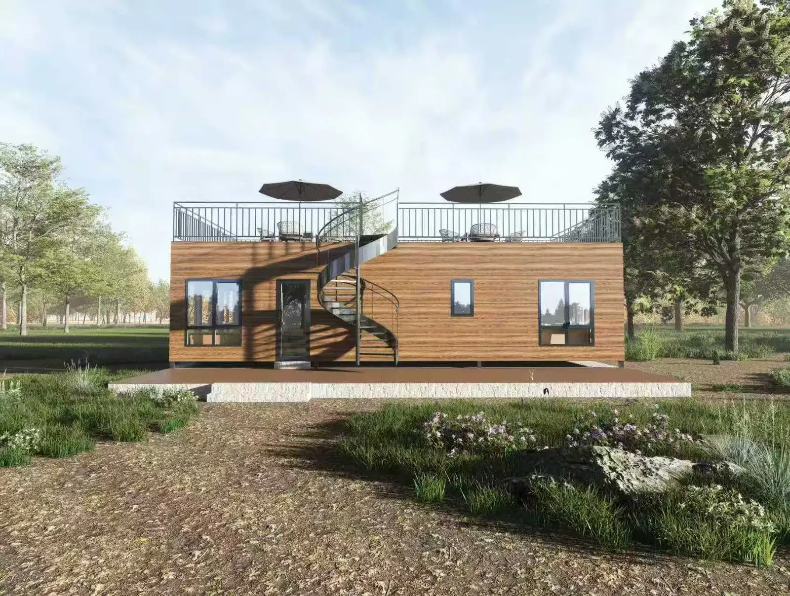
Engineering delivery / Missouri residences
Modular cabin engineering.
A live project, fully documented.
The Missouri lakeside residences are being delivered right now — and every number below comes from the working engineering model behind them.
- 1,154
- steel members positioned
- 69
- panels in the shipped kit
- 9,947
- code checks (AISI S100-16)
- 170
- installation steps
Interactive model
The real frame.
Member by member.
This is not an illustration — it is the project's coordination model. Orbit the residence, open the panel kit and inspect the checked steel frame.
How it is built
Built in the factory.
Assembled on site.
The building leaves the factory as finished assemblies — framed, serviced, insulated and lined — so the work in front of your guests is craning and connecting, not construction.
In the factoryIndoors, under inspection
- 01Panels assembled
Wall, floor, terrace and truss panels are jigged and fastened complete — framing, sheathing and bracing, not loose profiles.
- 02Services pre-installed
Electrical runs, drainage and plumbing for all three wet rooms are built into the panels and pressure-tested before anything closes.
- 03Insulation + linings
Insulation, membranes, linings and window frames are fitted into the panel indoors, with each step inspected.
- 04Inspected + packed
Every assembly is checked against the inspection plan, labelled, then crated in installation order.
On siteDays of assembly, not months of building
- 05Foundations ready
The local team sets out and completes the raft and pedestals before the containers sail.
- 06Modules set
Floor cassettes then wall and truss panels are craned into position and bolted — the building goes up in days, not months.
- 07Connections made
Panel joints, roof, terrace and the pre-installed service runs are connected at prepared interfaces and re-tested.
- 08Sealed + handed over
Weather line closed, close-out checks completed, and the document set handed over with the building.
Delivery documents
The paperwork is the product.
A project can be carried by a named document set generated from the same model and reviewed against the receiving site before release.
- Six-level BOM
The material breakdown traces from assemblies to panels, members and fasteners and is reconciled against the project material schedule.
- 170-step installation manual
Phase-gated sequence with crew sizes, durations and inspection checks, issued in English for the site team.
- Structural calculation book
9,947 member and connection checks against AISI S100-16 LRFD, kept with the model.
- Container loading plan
Panel kits packed into 2 × 40HC with centre-of-gravity and unload-order checks.
- QC + handover records
Factory release gates, site hold points, punchlist and the delivered document set.
Questions about the model
What does AeroPodHomes publish about the engineering of a project?
A positioned model rather than a description. For one Missouri reference residence that is 1,154 steel members placed in three dimensions, 1,426 resolved connections, 9,947 reported structural checks, 19 openings set out, a 69-panel factory kit and a 170-step installation sequence across 14 phases.
Is the 3D model on this page real project data?
It is generated from the working model of one Missouri reference residence. The geometry, panel split and opening positions shown belong to that reference; the approved project documents remain the controlling source for production and site work.
Which structural code is the design verified against?
AISI S100-16 for the light-steel structure. Destination compliance and final structural sign-off remain with the engineers of record appointed for each project and the relevant local authority — we supply the calculation record that supports their review.
What is a hold point, and who can stop the work?
A named gate in the installation sequence that requires a recorded check before the next phase begins — floors before walls, bracing before trusses, service tests before finishes. Both we and the client hold the authority to stop work at a gate. Warranty cover depends on the building having been installed to the issued manual with those records kept.
Can we see the engineering documents before ordering?
The document set is issued for your own project: a six-level bill of materials, a structural calculation book, a container loading plan and the step-sequenced installation manual. Sample extracts are walked through during project review. The method behind the model is not published.
Take it further